Brand:FOXBORO
Model: 3300/16
Status: New/Used
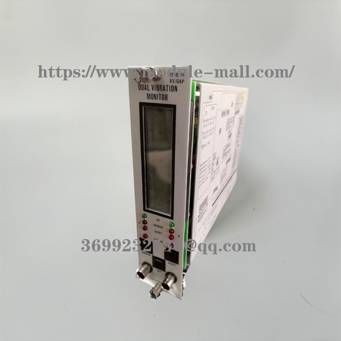
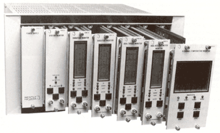
BENTLY NEVADA 3300/16 Dual Vibration Monitor
BENTLY NEVADA 3300/16
BENTLY NEVADA 3300/16 Dual Vibration Monitor
RADIAL VIBRATION - Radial vibration is defined as shaft dynamic motion in a directionperpendicular to the shaft centerline. The Dual Vibration Monitor displays values for twochannels (Channel A and B).
OK - When the Proximitor output voltage is within its upper/lower limits, the transducer is defined as OK. The OK detection circuit controls the channel OK LED and the monitor relay drive to the system Relay.OK RELAY - The OK Relay is located on the Power Input Module. Every channel in the rack must be OK or bypassed to energize the OK Relay.
TIMED OK/CHANNEL DEFEAT - Timed OK/Channel Defeat prevents faulty transducer wiring from causing false alarms. If the probe input signal level on a given channel is not within upper/lower OK limits, that channel OK LED goes off, the BYPASS LED goes on, the channel is disabled, and the OK Relay deenergizes. Once the channel input signal level is restored within the upper/lower OK limits for at least 30 seconds, the channel OK LED will start flashing at 1 Hertz (Hz) to indicate the OK state is restored, the BYPASS LED goes off, and monitoring is enabled. You must press the RESET switch on the front panel of the System Monitor to stop the OK LED from flashing (it will then remain on steadily). If the channel remains in the not OK state, set the Channel Bypass switch on the monitor circuit board to put the channel "out of service". You can then operate the monitor as a single-channel monitor, and the OK Relay will return to an OK state (energized). Without this feature, the OK Relay could not be reactivated. In the Timed OK/Channel Defeat and Channel Bypass modes, the recorder output is clamped to zero vibration value and the display is clamped to zero.
VIBRATION ALARM - Pressing the ALERT or DANGER switches on the front panel of the monitor displays the Alert (first-level alarm) or Danger (second-level alarm) vibration setpoints on the front panel meter. When the radial vibration signal level is equal to or exceeds preset Alert setpoints for the selected time delay, the ALERT LEDs come on and the appropriate Alert Alarm relay contacts are activated. When the radial vibration signal level exceeds preset Danger setpoints, the DANGER LEDs come on and the appropriate Danger alarm relay contacts are activated.
3300/16 Dual Vibration Monitor Operation Manual
GAP ALARM - Pressing the GAP and ALERT switches simultaneously displays the Gap Alert setpoints. When the gap level is equal to or outside the over and under setpoint window limits for 6 seconds, the ALERT LEDs come on and the appropriate Alert Alarm relay contacts are activated.
ALARMS RELAYS - Monitor alarms can operate in a latching or nonlatching mode. In the nonlatching mode, the alarm resets automatically when the alarm no longer exists. In the latching mode, you must reset the alarm condition manually by pressing the RESET switch on the front panel of the System Monitor (or by closing external Reset contacts). The alarm will not reset if the alarm condition still exists.
DANGER BYPASS - When you maintain machinery, you can set a Danger Bypass switch on the monitor circuit board behind the front panel to inhibit the Danger relay drive. This function causes the BYPASS LEDs to come on, but other front panel functions are not affected. You can enable this switch by installing a jumper on the circuit board in the monitor.
CHANNEL BYPASS - If a channel remains not OK, you can set the Channel Bypass switch on the monitor circuit board to put the channel "out of service".
ZERO POSITION - A reference gap value that you can set when the Gap Full Scale Range is in engineering units (mils or micrometers). You can then read gap on the meter scale relative to this zero position on the center of the gap meter scale. Selecting a Gap Full Scale Range in engineering units increases gap resolution on the display because only a selected area within the transducer's OK limits is displayed. BUFFERED OUTPUT - The coaxial cable connectors on the front panel of the monitor and the terminals on the Signal Input Relay Module provide buffered signals from the respective channel transducers. Use these connectors to attach external equipment to the monitor.
TRIP MULTIPLY - The Trip Multiply function multiplies setpoints by 2X or 3X in response to an external contact closure through terminals on the Power Input Module. The front panel meter and recorder outputs could saturate in this mode.
RECORDER OUTPUTS - The recorder output is proportional to the measured vibration signal over the monitor full-scale range. The output range is user selectable to be 0 to - 10Vdc, +1 to +5Vdc, or +4 to +20 mA.
The recorder clamping option, available when the +4 to +20 mA recorder output is selected, allows the user to choose the recorder output level used to annunciate a transducer not OK condition. With this option, the recorder output will clamp to either +2 mA or +4 mA (user selectable) when a transducer is not OK.
SELF-TEST - The monitor has three categories of self-test: Power-up, Cyclic, and User- invoked.
Power-up self-test is performed automatically each time the monitor power is turned on. A series of basic tests and transducer OK tests are performed.
Cyclic self-test is performed automatically during monitor operation. Errors encountered during cyclic tests disable the monitor and flash the error code on the LCD bargraph. If the error is intermittent, the monitor will resume operating, but the error codes will be stored for retrieval during a User-invoked self test. Stored error codes are indicated by the OK LEDs flashing at 5 Hz provided that the channel is OK.
User-invoked self-test performs the Power-up self test and lets you read and clear error codes stored during cyclic tests. Stored errors are annunciated by flashing the OK LEDs at 5 Hz and displaying the error codes on the front panel LCD bargraph.
Other models: 3300/03 , 3300/05 , 3500/10 , 3300/12 , 3300/15 , 3300/16 , 3300/20, ,3300/25 , 3300/40 , 3300/45 , 3300/50 , 3300/55 , 3300/65