Brand:PROSOFT
Model: MVI69E-MBS
Status: New/Used
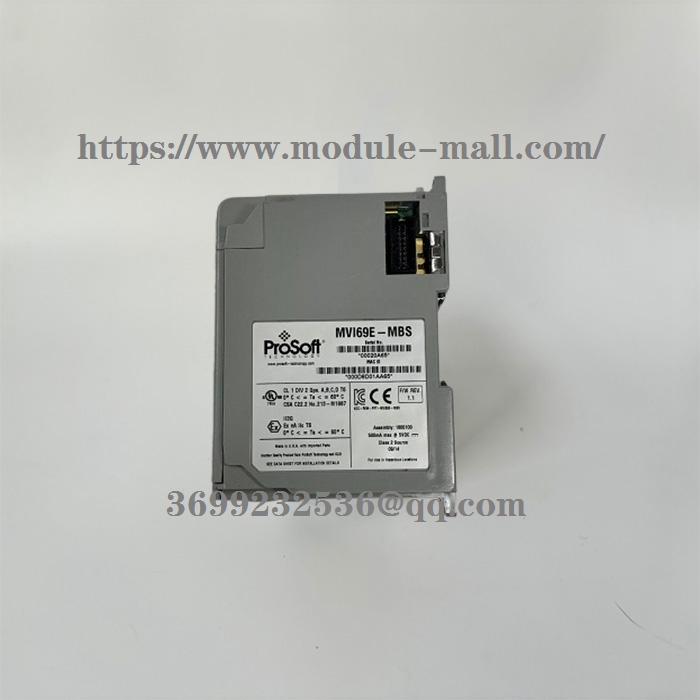
PROSOFT MVI69E-MBS CompactLogix™ PlatformModbus Serial Enhanced CommunicationModule
PROSOFT MVI69E-MBS
PROSOFT MVI69E-MBS CompactLogix™ PlatformModbus Serial Enhanced CommunicationModule
System Requirements
The MVI69E-MBS module requires the following minimum components:
• Rockwell Automation CompactLogix or MicroLogix 1500-LRP® processor (firmware version 10 or higher), with compatible power supply.
Important: The MVI69E-MBS module has a power supply distance rating of 4 (L43 and L45 installations on first 2 slots of 1769 bus). It consumes 500 mA at 5 VDC.
Important: For 1769-L23x processors, please make note of the following limitation: 1769-L23E-QBFC1B = 450 mA at 5 VDC (No MVI69E module can be used with this processor.)
• The module requires 500 mA of available 5 VDC power
• Rockwell Automation Studio 5000 Logix Designer programming software
• Rockwell Automation RSLinx® communication software version 2.51 or higher
• ProSoft Configuration Builder (PCB) (included)
• ProSoft Discovery Service (PDS) (included in PCB)
• Pentium®II 450 MHz minimum.
• Supported operating systems:
Microsoft Windows® 10 Professional
Microsoft Windows® 7 Professional
Microsoft Windows® XP Professional
• 128 Mbytes of RAM minimum, 256 Mbytes of RAM recommended
• 100 Mbytes of free hard disk space
• 256-color VGA graphics adapter, 800 x 600 minimum resolution
Setting Jumpers
When the module is manufactured, the port selection jumpers are set to RS-232. To use RS-422 or RS-485, you must set the jumpers to the correct position. The following diagram describes the jumper settings.
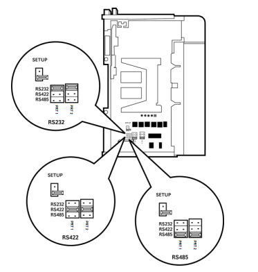
Note: Jumper pin placement on the circuit board may vary.
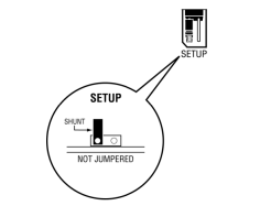
The Setup Jumper acts as "write protection" for the module’s firmware. In "write protected" mode, the Setup pins are not connected, and the module’s firmware cannot be overwritten. The module is shipped with the Setup jumper OFF. If an update of the firmware is needed, apply the Setup jumper to both pins.
The following illustration shows the MVI69E-MBS jumper configuration, with the Setup Jumper OFF.
Installing the Module in the Rack
Make sure the processor and power supply are installed and configured before installing the MVI69E-MBS module. Refer to the Rockwell Automation product documentation for installation instructions.
Warning: Please follow all safety instructions when installing this or any other electronic devices. Failure to follow safety procedures could result in damage to hardware or data, or even serious injury or death to personnel. Refer to the documentation for each device to be connected to verify that suitable safety procedures are in place before installing or servicing the device.
After you verify the jumper placements, insert the MVI69E-MBS into the rack. Use the same technique recommended by Rockwell Automation to remove and install CompactLogix or MicroLogix 1500-LRP modules.
Warning: This module is not hot-swappable! Always remove power from the rack before inserting or removing this module, or damage may result to the module, the processor, or other connected devices.
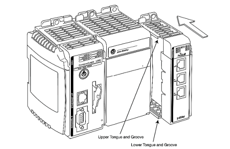
1 Align the module using the upper and lower tongue-and-groove slots with the adjacent module and slide forward in the direction of the arrow.
2 Move the module back along the tongue-and-groove slots until the bus connectors on the MVI69 module and the adjacent module line up with each other.
3 Push the module’s bus lever back slightly to clear the positioning tab and move it firmly to the left until it clicks. Ensure that it is locked firmly in place.
4 Close all DIN-rail latches.
5 Press the DIN-rail mounting area of the controller against the DIN-rail. The latchesmomentarily open and lock into place