Brand:PROSOFT
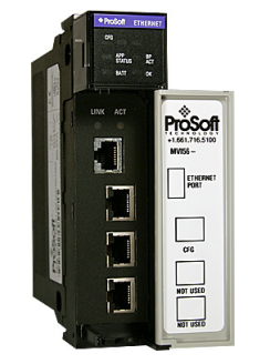
Model: MVI56-MNETR
Status: New/Used
PROSOFT MVI56-MNETR Modbus TCP/IP Interface Module withReduced Data Block
PROSOFT MVI56-MNETR
PROSOFT MVI56-MNETR Modbus TCP/IP Interface Module withReduced Data Block
System Requirements
The MVI56-MNETR module requires the following minimum hardware and software components:
Rockwell Automation ControlLogix™ processor, with compatible power supply and one free slot in the rack, for the MVI56-MNETR module. The module requires 800 mA of available power.
Rockwell Automation RSLogix 5000 programming software version 2.51 or higher
Rockwell Automation RSLinx communication software
Pentium® II 450 MHz minimum. Pentium III 733 MHz (or better) recommended
Supported operating systems:
• Microsoft Windows XP Professional with Service Pack 1 or 2o
• Microsoft Windows 2000 Professional with Service Pack 1, 2, or 3o
• Microsoft Windows Server 2003
128 Mbytes of RAM minimum, 256 Mbytes of RAM recommended
100 Mbytes of free hard disk space (or more based on application requirements)
256-color VGA graphics adapter, 800 x 600 minimum resolution (True Color 1024 × 768 recommended)
CD-ROM drive
ProSoft Configuration Builder, HyperTerminal or other terminal emulator program.
Note: You can install the module in a local or remote rack. For remote rack installation, the module requires EtherNet/IP or ControlNet communication with the processor.
Installing the Module in the Rack
If you have not already installed and configured your ControlLogix processor and power supply, please do so before installing the MVI56-MNETR module. Refer to your Rockwell Automation product documentation for installation instructions.
Warning: You must follow all safety instructions when installing this or any other electronic devices. Failure to follow safety procedures could result in damage to hardware or data, or even serious injury or death to personnel. Refer to the documentation for each device you plan to connect to verify that suitable safety procedures are in place before installing or servicing the device.
After you have checked the placement of the jumpers, insert MVI56-MNETR into the ControlLogix chassis. Use the same technique recommended by Rockwell Automation to remove and install ControlLogix modules.
Warning: When you insert or remove the module while backplane power is on, an electrical arc can occur. This could cause an explosion in hazardous location installations. Verify that power is removed or the area is non-hazardous before proceeding. Repeated electrical arcing causes excessive wear to contacts on both the module and its mating connector. Worn contacts may create electrical resistance that can affect module operation.
1 Turn power OFF.
2 Align the module with the top and bottom guides, and slide it into the rack until the module is firmly against the backplane connector.
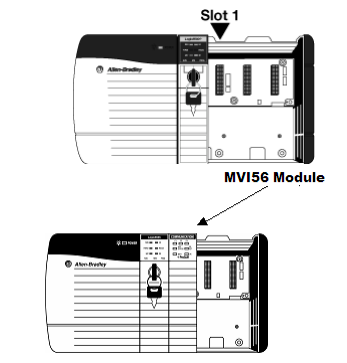
3 With a firm but steady push, snap the module into place.
4 Check that the holding clips on the top and bottom of the module are securely in the locking holes of the rack.
5 Make a note of the slot location. You must identify the slot in which the module is installed in order for the sample program to work correctly. Slot numbers are identified on the green circuit board (backplane) of the ControlLogix rack.
6 Turn power ON.
Note: If you insert the module improperly, the system may stop working, or may behave unpredictably.