Brand:ICS Triplex
Model: T8110B
Part No:
Status: New/Used
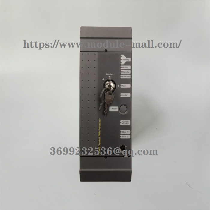
ICS Triplex T8110B TMR processor
ICS Triplex T8110B
ICS Triplex T8110B TMR processor
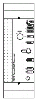
The front panel of the TMR processor is equipped with status and diagnostic LED indicators, a reset button, and a maintenance enable key switch.
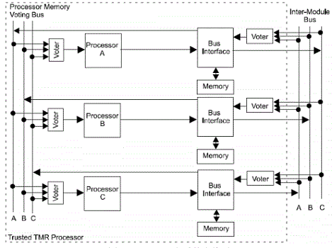
The TMR processor adopts a fault-tolerant design based on step locked synchronization TMR structure. The module includes three Processor Fault Restricted Zones (FCRs), each processor consisting of a Motorola PowerPC series processor and associated memory. Each processor fault limited area (FCR) accesses the memory system of the other two processor fault limited areas through a 3-to-2 vote to eliminate system bias operations.
The three processors of the module simultaneously store and execute application programs, scan and update I/O modules, and detect system failures. Each processor executes the application independently, but is always in step locked synchronization with the other two processors. If one of the three processors deviates, additional mechanisms will allow the faulty processor to resynchronize with the other two processors.
The front panel contains a fault restriction area that includes non critical single function separated from other FCRs. These features include diagnostic ports installed on the front panel of the processor and maintenance enable key switches. Other functions in the front panel FCR include serial communication driver and IRIG-B interface.
Each processor and Fault Restricted Zone (FCR) receives internal voltage from the dual redundant+24VDC power supply on the controller rack backplane through module connectors.
The voting circuit reads input data from the inter module bus and performs continuous 3-to-2 voting on the data. When a fault occurs, the voting circuit and fault detection circuit enable the module to detect and isolate momentary, intermittent, and permanent faults. All faults are recorded in the system's fault history. Permanent faults are indicated by the LED indicator lights on the front panel of the module.
In the system power failure mode, system data, fault information, and user program data are retained in the non-volatile memory of the TMR processor, powered by a non replaceable battery for up to 10 years.
The communication between the TMR processor and the I/O modules in the expansion rack is achieved through the expansion interface module in the controller rack.
Processor configuration
The entire system software configuration in the processor memory must be consistent with the hardware configuration of the system. TMR processors can be processed through one or two methods
The method communicates and is configured with the engineer station.
1. Communicate with the engineer station through the diagnostic interface on the front panel. The communication rate for diagnosing the fracture is 19.2kb/s
2. Communicate with the engineer station through the communication interface module. The communication interface module supports serial communication and Ethernet communication, however, TOOLSET software (workstation) can only communicate with the communication interface module through Ethernet.
RESET
The fault indication will be locked. Pressing the fault reset button can reset all fault counters and clear all module fault indications. The reset action will be recorded in the logs of the microprocessor and I/O module. Depending on the size of the processor memory and the scanning time of the application, the time it takes for the system to complete a fault reset can vary from a few seconds to a few minutes. However, during the fault reset process, the system always continuously reads and writes I/O, executes application programs, and performs communication functions. The usual fault reporting function is enabled again after the reset is completed.
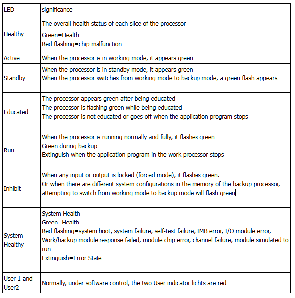
Module status LED indicator light
The front panel of the processor has 7 LED status indicators, 3 Healthy indicators, 1 Active indicator, 1 Educated indicator, 1 Run indicator, 1 SystemHealthy indicator, and 2 User indicators (User1 and User2). The Healthy indicator light is directly controlled by each slice of the processor. All LED indicator lights are controlled by the processor itself. The LED status and significance of the processor module
Maintenance/safety key switch
The key switch on the front panel is used to prevent unauthorized system access. The key switch has two position modes:
1. Run Run
2. Maintain Integrity
Memory is locked at runtime.
When the key switch is in the maintenance position and has the correct access authorization, applications and system configurations can be downloaded from the engineer station.
The key switch can be removed in two positions to prevent unauthorized use.
If the switch also has a momentary third position, but it has no function.
System Overview
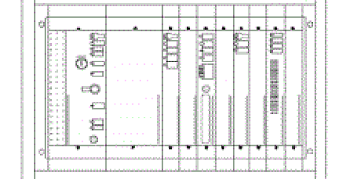
TRUSTED programmable controller consists of three main parts: controller part, expander part, and power supply part. In the controller
There are various triple modules in the parts and extender sections.
All triple modular units are installed in a 19 inch rack. The installation bracket allows for front panel installation and rear panel installation.
The communication between TRUSTED system and external systems can be achieved through the main processor, dedicated communication module, or gateway module. Multiple communication protocols can be used for serial communication and Ethernet communication. The communication module can be installed in the control rack and expansion rack.
Other models: T8100 ,T8110B ,T8110C ,T8151B ,T8160 ,T8191 ,T8193 ,T8231 ,T8300 ,T8310 ,T8311 ,T8402 ,T8403 ,T8403C ,T8431 ,T8431C ,T8451 ,T8451C ,T8461 ,T8461C ,T8480 , T8480C
Many products have not been launched yet. If you need more products, please contact us
Purchase consultation hotline: 18120742318